Primitives
The Primitives tool allows you to create, edit, and manage geometric primitive objects in your project. Primitives are idealized geometric shapes used for reference measurements, region-of-interest (ROI) definition, and geometric analysis.
Accessing the Tool
- Navigate to the Measure tab in the ribbon
- Click the Primitives button in the Primitive tools section
Primitive Types
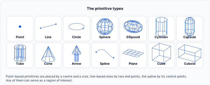
Select a primitive type from the dropdown menu before placing:
Point
Create a single reference point.
- Placement: Click once to place the point
- Use case: Mark reference positions, create point sets for fitting
Line
Create a line segment between two points.
- Placement: Click to place the first point, then click for the second point
- Use case: Define axes, directions, or reference lines
Circle
Create a planar circle.
- Placement: Click to set the center, then drag to define the radius
- Use case: Circular ROI, cross-section analysis
Sphere
Create a 3D sphere.
- Placement: Click to set the center, then drag to define the radius
- Use case: Spherical ROI, tumor delineation, anatomical landmarks
Ellipsoid
Create a 3D ellipsoid with three independent axes.
- Placement: Click to set the center, then drag to define the initial size
- Use case: Non-spherical anatomical structures, elongated ROIs
Cylinder
Create a cylinder along a specified axis.
- Placement: Click to place two points defining the axis and height
- Use case: Tubular structures, vessel analysis
Capsule
Create a capsule (cylinder with hemispherical caps).
- Placement: Click to place two points defining the axis
- Use case: Pill-shaped ROIs, rounded tubular structures
Tube
Create a hollow tube.
- Placement: Click to place two points defining the axis
- Use case: Hollow tubular structures, vessel walls
Cone
Create a cone with a specified apex and base.
- Placement: Click to place two points defining apex and base
- Use case: Conical structures, directional indicators
Arrow
Create an arrow indicator.
- Placement: Click to place two points defining direction
- Use case: Directional markers, flow indicators
Spline
Create a smooth curve through multiple points.
- Placement: Left-click to add control points, right-click to finalize
- Use case: Complex curved paths, anatomical tracing
Left-click to add control points, right-click to finalize the spline. The curve automatically smooths between control points using interpolation.
Plane
Create an infinite reference plane.
- Placement: Click to set the origin, then drag to orient
- Use case: Cutting planes, reference surfaces, alignment
Cube
Create a cube with equal dimensions.
- Placement: Click to set the center, then drag to define size
- Use case: Cubic ROI, regular sampling volumes
Cuboid
Create a box with independent dimensions on each axis.
- Placement: Click to set the center, then drag to define size
- Use case: Rectangular ROI, bounding regions
User Interface
Description Group
Displays instructions for the currently selected primitive type.
Primitive Dropdown
Select the primitive type to create from the dropdown menu.
Primitives Table
Lists all primitives in the project. The table uses the same layout as the Measurements table.
| Column | Description |
|---|---|
| Show | Visibility toggle for the primitive |
| Lock | Lock toggle, which protects a placed primitive from being edited or dragged |
| Name | Editable primitive name |
| Value and coordinate columns | The primitive's defining values, shown for the types that have them |
Toolbar Buttons
| Button | Tooltip |
|---|---|
| Add (+) | Add a new primitive. |
| Remove (-) | Delete the selected primitive(s). |
| Clear | Delete all primitives. |
| Move up | Move the selected primitive up. |
| Move down | Move the selected primitive down. |
| Save | Save primitives to the disk. |
| Load | Import primitives from the disk. |
| More (...) | Open the display options menu described below |
Right-Click Menu
Right-clicking a row offers the same commands as the Measurements table: Select All, Invert Selection, Toggle Visibility, Isolate, Toggle Lock, Isolate Unlock, Locate, Copy, Duplicate, Move Up, Move Down, Remove Selected, and Properties.
More Options Menu
The ... button opens the display options, which match the Measurements More Options menu with one addition:
| Option | Description |
|---|---|
| Always Show | Keep primitives visible when the tool is closed |
| Show In Slice Views | Display primitives in the 2D slice views |
| Annotation | Which annotations are shown, and what they contain |
| 3D Axes | Visibility of the 3D crosshair drawn at each primitive |
| Handle | Show 2D Cross and Show Point control how the handles are drawn |
| Surface | Snap To Surface... snaps the primitive's points onto a surface, and Copy To Surfaces converts the selected primitives into surface objects in the scene tree |
| Properties... | Open the property dialog for the selected primitive |
Copy To Surfaces is the quickest way to bring an exact analytical shape, for example a fitted sphere or cylinder, into the surface workflow, where it can be used for Boolean operations, meshing, or export.
Workflow
Creating a Primitive
- Select the desired primitive type from the dropdown
- Click the Add (+) button to enter placement mode
- Click in a 2D or 3D view to place the primitive
- For drag-based primitives, hold and drag to define the size
- For multi-point primitives, click additional points as needed
Editing Primitives
After creation, primitives can be manipulated using the 3D gizmo:
- Move: Drag the gizmo center to translate
- Rotate: Drag rotation handles to orient
- Scale: Drag scale handles to resize
Locating Primitives
Select a primitive in the table, right-click, and choose Locate to center all views on that primitive.
Properties and Appearance
Visual Properties
Primitives have the following default appearance:
- Color: Cyan (0, 1, 0.9)
- Opacity: 100%
- Wireframe: Solid (not wireframe)
Follow Object Profile
When enabled, primitive visibility updates based on the current slice plane positions, showing only the portion of the primitive that intersects the visible slice.
Import and Export
Supported Formats
Primitives can be saved and loaded using the INI settings format (.ini), preserving:
- Primitive type and name
- Position and orientation
- Dimensions and parameters
- Visual properties
Primitive export files use a human-readable INI format to support transparency, interoperability, and reproducibility. This allows external tools and scripts to process ROI data when needed.
Exporting Primitives
- Click the Save button in the toolbar
- Choose a location and filename
- Select "Settings (*.ini)" as the file type
- Primitives are saved with an integrity checksum
Importing Primitives
- Click the Load button in the toolbar
- Select a previously saved primitives file
- Primitives are added to the current project
- Volvicon automatically verifies file integrity on import
Data Integrity Verification
Volvicon includes data integrity verification for primitive/ROI export files to ensure data traceability and detect external modifications.
How It Works
When you export primitives:
- Volvicon computes a SHA-256 cryptographic hash of all primitive data
- The hash is stored in a dedicated
[Integrity]section of the exported file - This process is automatic and transparent to the user
When you import primitives:
- Volvicon recomputes the hash from the file content
- The computed hash is compared with the stored hash
- Any mismatch indicates the file was modified externally
Integrity Status
| Status | Description |
|---|---|
| Verified | File integrity confirmed—data has not been modified since export |
| Modified | Hash mismatch detected—file was altered outside Volvicon |
| No Hash | Integrity section missing or removed—integrity cannot be verified |
If a file is detected as modified, Volvicon displays a warning:
"This measurements file was modified outside Volvicon. Measurement accuracy and validity cannot be guaranteed."
The import proceeds, but you should verify the ROI definitions before relying on them for analysis.
File Structure
Exported primitive files include:
[Document]
ApplicationName=Volvicon
ApplicationVersion=x.x.x
DateTime=2026-01-30 12:00:00

[PrimitiveObjects]
; ... primitive data ...

[Integrity]
FormatVersion=1.0
IntegrityHash=SHA256:9f3a8c...e21
Regulatory Considerations
The integrity verification system supports regulatory requirements for data traceability:
- Tamper Detection: Any modification to ROI data is detected on import
- Audit Trail: Integrity status is logged for debugging and audit purposes
- User Notification: Clear warnings ensure users are informed of data modifications
- No Data Blocking: Modified files can still be imported—users retain full control
For regulatory submissions (FDA, CE), maintain the original exported files without modification. If adjustments are needed, re-export from Volvicon to generate a new verified file.
Scripting
Primitives can be created and manipulated programmatically:
import ScriptingApi as api

app = api.Application()
primitive_operations = app.get_primitive_operations()

# Create a sphere
primitive_operations.create_sphere([0, 0, 0], 10, "Sphere_1")

# Create a cylinder
primitive_operations.create_cylinder([0, 0, 0], [0, 0, 50], 5, "Cylinder_1")

# Get all sphere primitives
spheres = primitive_operations.get_primitive_names_by_type(api.PrimitiveType.Sphere)
See the Primitive Operations API for the complete function reference.
Related Tools
- Measurements — Point-based measurements
- Primitive Fitting — Fit primitives to geometry automatically
- Measurement between Primitives — Measure between primitive objects