3D Visualization Techniques
Effective visualization communicates the content and structure of your data. This tutorial covers advanced rendering techniques, including volume rendering, surface shading, clipping operations, and camera controls for creating publication-quality images.
Estimated time: 30 minutes
Prerequisites:
- Completed basic tutorials
- A project with volumes, masks, and/or surfaces
Volume Rendering Concepts
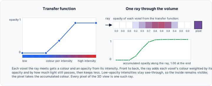
Volume rendering displays 3D data by calculating how light interacts with the entire dataset—not just surfaces. Each voxel contributes to the final image based on its intensity and assigned visual properties.
Key concepts:
- Transfer Function — Maps intensity values to color and opacity
- Opacity — How transparent each intensity appears
- Sampling — How many rays pass through the volume
- Shading — Lighting calculations for depth perception
Configuring Volume Display
Window/Level Adjustment
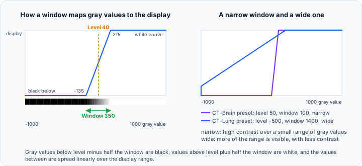
The fundamental visualization control:
- Navigate to View → Slice Views → Window/Level.
- Adjust:
- Level — Center intensity (brightness)
- Window — Intensity range (contrast)
Interactive adjustment:
- Hold Left mouse button and drag in slice views
- Horizontal: Window | Vertical: Level
Lookup Tables (LUTs)
Apply color mapping to intensity values:
- In the Window/Level panel, select a Lookup Table.
- Available options include:
- Grayscale — Standard medical imaging
- HotMetal — Fire-like warm colors
- Spectrum — Full spectrum
- Jet — Blue-cyan-yellow-red
LUTs enhance visualization of:
- Intensity gradients
- Analysis results
- Presentation graphics
Mask 3D Preview
Use one of the two mask preview modes depending on whether you need a calculated surface or immediate 3D updates:
- Navigate to View → 3D View.
- For a surface preview, use Mask 3D Preview (Mesh) and select a quality level:
| Quality | Description | Use Case |
|---|---|---|
| Low | Fast, coarse | Quick exploration |
| Medium | Balanced | General review |
| High | Enhanced detail | Special applications |
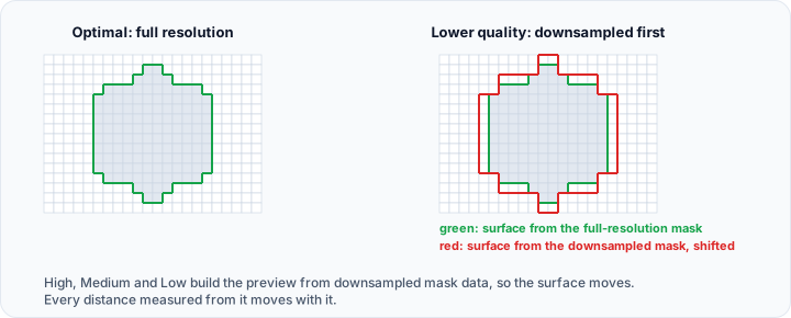
| Optimal | Full resolution | Measurements, export |
- Click Mask 3D Preview (Mesh) to generate.
For immediate 3D feedback while editing, enable Mask 3D Preview (Direct) instead. Direct mode renders mask voxels as a volume, does not create a surface mesh, and is turned off automatically when you generate a mesh preview.
Use Optimal quality when performing measurements on mask previews. Lower quality settings use downsampled data that may introduce geometric error.
Managing Previews
- Remove All Previews — Clear generated previews to free memory
- Existing mesh previews can regenerate automatically after edits if enabled in Preferences
- Direct preview updates immediately from the mask volume and does not regenerate a mesh
Surface Representation Modes
Control how surfaces appear in the 3D view:
| Mode | Key | Description |
|---|---|---|
| Solid | S | Filled, shaded surfaces |
| Solid Edges | E | Filled with visible triangle edges |
| Wireframe | W | Triangle edges only |
| Points | Q | Vertices only |
Access from View → 3D View → Surface Representation or use keyboard shortcuts.
Shading Algorithms
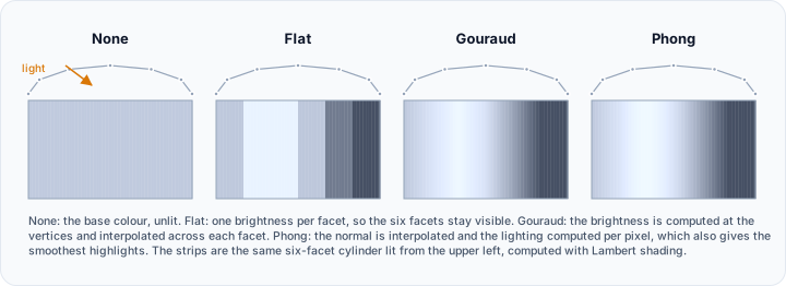
Configure lighting calculations:
| Algorithm | Appearance |
|---|---|
| None | Flat, unlit |
| Flat | Per-face shading |
| Gouraud | Smooth vertex interpolation |
| Phong | Per-pixel highlights |
| PBR | Physically based rendering |
Access from View → 3D View → Surface Shading.
Phong provides good quality for most applications. Use PBR for realistic material appearance in presentations.
Lighting Configuration
Proper lighting enhances depth perception and surface detail.
Light Studio
- Navigate to View → Camera → Light Studio.
- Orbit to the viewpoint you want to light.
- Choose Presets → Three-Point Studio for a balanced starting point.
- Select the key, fill, or back light to adjust it. The preset enables Cast shadows only on the key light so the scene has one coherent shadow direction.
Light Properties
For each light:
| Property | Effect |
|---|---|
| Intensity | Brightness level |
| Diffuse, specular, and ambient color | Surface illumination, highlights, and ambient tint |
| Position | Location relative to scene |
| Type | Scene light, camera light, or headlight |
| Positional light | Changes a directional light to a positioned spotlight or point light |
| Cast shadows | Allows the selected scene or camera light to produce mapped shadows |

For examining surface detail, use a strong key light from a side angle. For softer presentation images, reduce the fill light rather than enabling shadow casting on every light. See the complete Light Studio guide for manipulators, presets, floor shadows, and reusable JSON setups.
3D Clipping
Reveal internal structures by removing portions of the display.

Enable Clipping
- Navigate to View → 3D Clipping → Enable.
- The clipping box activates.
- Content outside the box is hidden.
Adjust the Clipping Box
- Click Show Box to display interactive handles.
- Drag face handles to resize along each axis.
- Drag edges or corners for multi-axis adjustment.
Clipping Options
| Option | Effect |
|---|---|
| Enable | Toggle clipping on/off |
| Show Box | Display/hide interactive handles |
| Invert | Show outside instead of inside |
| Reset | Return to full scene bounds |
Clipping Workflow Example
To create a cross-section view:
- Enable clipping.
- Show the box.
- Drag one face to cut through your structure.
- Hide the box for clean presentation.
- Rotate the view to examine the cross-section.
Camera Controls
Standard Orientations
Quick camera positioning using keyboard shortcuts:
| Key | View |
|---|---|
| X | Right (+X) |
| Shift+X | Left (-X) |
| Y | Front (+Y) |
| Shift+Y | Back (-Y) |
| Z | Top (+Z) |
| Shift+Z | Bottom (-Z) |
| I | Isometric |
Or access from View → Camera → Standard Views.
Projection Modes
| Mode | Characteristics |
|---|---|
| Perspective | Objects appear smaller with distance (realistic) |
| Parallel | Objects maintain size regardless of distance (technical) |
Press V to toggle between modes.
Camera Settings
- Navigate to View → Camera → Camera Settings → 3D View.
- Configure:
- View angle — Field of view (perspective mode)
- Clipping range — Near/far rendering limits
- Focal point — Center of rotation
Center of Rotation
Set a custom rotation center:
- Position mouse over the point of interest.
- Press C to set it as the center of rotation and center that point in the 3D view.
- Subsequent rotations orbit this point.
Object Visibility and Widgets
Scene Tree Controls
For each object in the Scene Tree:
- Visibility icon — shows or hides the object in the views
- Click the name — selects the object and makes it the active object of its type, shown in bold. Tools that work on "the active mask" or "the active volume" use it
- Double-click the name — renames the object in place
- Right-click — opens the operations for that object type, including visibility, isolate, duplicate, export, rename, delete, and render properties
Object Widgets and Scene Helpers
The 3D View section of the View tab holds these scene helpers:
| Control | Description |
|---|---|
| Additional → Object Widgets → Toggle Outline | Bounding box around visible objects, per object type |
| Additional → Object Widgets → Toggle Corner Outline | Corner markers instead of a full box, per object type |
| Slice Planes | Shows the slice planes of the active volume in the 3D view, and can use one as a clip plane |
| Axes Planes | Reference planes along the principal axes |
Object Widgets carries a submenu for Volume, Surface, and Volume Mesh, so each object type can be outlined on its own. Additional also holds Colors, which draws surface objects with their own color data.
Capturing Images
Screenshots
Capture static images of the current view:
- Navigate to File → Save Screenshot.
- Select target:
- Application — Entire window
- 3D View — 3D viewport only
- Specific View — Individual view panel
- Choose destination (file or clipboard).
- Configure:
- Format — PNG, JPEG, BMP
- Click Capture.
Video Recording
Create animations with the Video Recorder panel:
- Navigate to File → Media → Record Video to open the Video Recorder at the bottom of the window.
- Configure:
- Target view — Which view to record
- Animation — Interactive (live), turntable rotation, rock, camera path (keyframes), slice sweep, or a timeline of multiple tracks (camera, opacity, clipping, slices, background)
- Duration and frame rate — Length and smoothness of the animation
- Quality, format, and folder — Output resolution, MP4/AVI format, and save location
- Click Preview to check the animation in the view without recording.
- Click Record. Animated recordings are rendered frame by frame and saved automatically when they complete. For Interactive (live), click Stop when finished.
Creating Presentation Views
Multi-Structure Visualization
When displaying multiple structures:
- Assign distinct colors to each surface/mask.
- Consider opacity:
- Outer structures: Lower opacity (0.3-0.5)
- Inner structures: Higher opacity (0.7-1.0)
- Use clipping to reveal internal relationships.
Publication-Quality Images
For journal figures or presentations:
- Maximize 3D view — Use 3D Only layout.
- Set high resolution — Configure screenshot for publication DPI.
- Use white/transparent background — Works better in documents.
- Apply consistent lighting — Phong or PBR shading.
- Remove distracting elements — Hide widgets, use clean representation.
Practical Exercise: Create a Visualization
Part 1: Configure Display
- Load a project with a bone mask and soft tissue.
- Generate 3D preview for both masks.
- Set bone color to white/ivory.
- Set soft tissue color to pink with 50% opacity.
- Apply Phong shading.
Part 2: Create Views
- Use clipping to create a cross-section.
- Capture a screenshot.
- Switch to isometric view (I key).
- Capture another screenshot.
- Create a 360° rotation video.
Part 3: Optimize for Export
- Maximize the 3D view.
- Hide the clipping box.
- Set white background.
- Capture high-resolution image.
Best Practices
Visualization Goals
| Purpose | Approach |
|---|---|
| Exploration | Standard lighting, quick preview |
| Measurement | Optimal quality, no distortion |
| Presentation | Polished lighting, clean background |
| Publication | High resolution, consistent style |
Performance
- Use lower quality previews during exploration
- Reduce triangle count for faster rendering
- Disable widgets when not needed
- Close unused views to allocate resources
Consistency
- Document your visualization settings
- Create presets for repeated workflows
- Use consistent coloring across related projects
Troubleshooting
Display appears black
- Check Window/Level settings
- Verify object visibility in the Scene Tree
- Reset the view (press R)
Slow rendering
- Reduce preview quality
- Decimate surfaces
- Hide unnecessary objects
Colors appear wrong
- Check lookup table selection
- Verify Window/Level range
- Review light colors and enabled lights in Light Studio
Next Steps
Continue learning with:
- Measurements and Statistics — Quantitative analysis
- Quality Analysis — Wall thickness and deviation